Making the remote controlThese are the instructions showing how I made a remote control for Canon's EOS Elan IIE. Please read all sections before embarking on the task of making your own. I take no responsibility for any accidents, errors, or misfortune that may occur if you embark on this project, although if you want to tell me about them feel free to email me - especially if you have ideas which could improve this site. My remote control has been fully tested with my Elan IIE and will hopefully continue to work for many years to come. As far as I know, the design should work with EOS Elan II / 50 / 50E, and may work with other EOS bodies that use the same remote control socket, but obviously I make no guarantees about that. 1. Preparing the box |
|
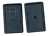
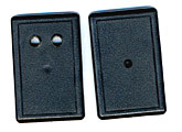
a) Dismantle the box. We need to make two holes to hold the push switches. Mark the position of these holes on the front of the box like this: b) Drill out the holes to the correct dimension for the push switches being used. If you don't have access to a drill, drive a small nail through the box where you've marked, pull the nail out and then use a large screw to open up the hole until it's large enough to accomodate the push switch. You may have to use a craft knife to tidy up the hole once it is large enough. |
|
|
c) A hole is required at the bottom of the box to allow the
control cable to exit. Mark a hole at the bottom of the box just
large enough to fit the headphone wire through (if it is just a
bit smaller it will grip the wire ensuring it does not move around
and possibly loosen connections inside the box).
You may find it easiest to mark the hole with the box halves
assembled, then dismantle the box and use a craft knife to cut
out the hole. d) A similar hole is required at the top of the box to hold the toggle switch. In a similar manner to the hole for the control cable, mark and carve out a hole at the top of the box. |
|
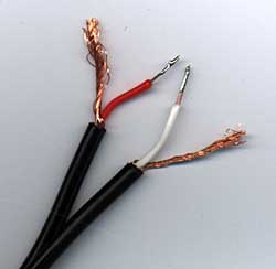
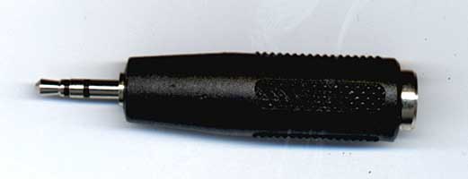
2. Soldering wires inside the boxa) Take one end of the stereo headphone cable. If you bought a pre-assembled cable with a plug at one end and a jack at the other, cut off the jack, but leave the plug at the other end intact, like this. Strip the cable to prepare the wires for soldering. b) If you're using a pre-assembled cable, you need to determine which wires are connected to the tip, ring and sleeve of the plug. The easiest way to do this is with a multimeter. Alternatively, connect the plug into the camera body via the adapter and experiment with connections to determine which wire is which. Ensure there is no film in the camera. Turn the camera on and connect pairs of wires together until you see AF/AE activated on the camera. The two wires connected are sleeve and ring. Take a third wire (your cable probably has four) and connect to the first two wires. If nothing happens, that third cable is likely another sleeve (ground) connection, so then try the fourth wire. Otherwise, the camera shutter should release, indicating that the third wire is the tip. c) Solder the wires to the switch connectors. The AF connection (ring) needs to be wired to one side of each of the three switches. The ground (sleeve) should be wired to the the non-AF side of the AF momentary switch, and the AF toggle switch. The shutter (tip) should be wired to the non-AF side of the shutter momentary switch. d) Before closing the box, fully test the remote operation. [Back: Theory of operation | Main Remote Page | Forward: Using the remote] Copyright (C) 1998-2004 Chantal Currid. [Home Page] |
|